


Application Illustrations
|
Chlorinators shown in the illustrations are from the Hidro system Models 500/502 series, which have a maximum capacity of 100 pounds of gas per day (PPD), or 2,000 grams of gas per hour (GPH). Higher capacity systems are configured in identical ways. These include the Models 200/202 series having a maximum capacity of 200 PPD or 4,000 GPH, and the still higher capacity Models 700/750 series having a maximum capacity of 500 PPD or 10,000 GPH. Hidro system sulfonator systems are configured in identical ways and are available in the same capacity levels. |
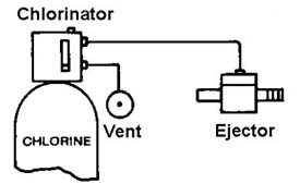
Single Point Application :
A Hidro system chlorinator/sulfonator with an internal meter directly connected to an ejector feeding a pipeline or basin.
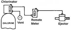
Single Point Application using a remote meter
|
A Hidro system chlorinator/sulfonator connected to a single wall mounted remote meter and ejector |
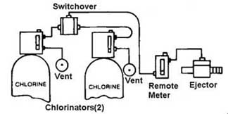
Single Point Application using an Automatic Switchover Standby
Two Hidro system chlorinator/sulfonators, connected to a switchover unit feeding one remote meter and ejector. When the current supply tank empties, the switchover unit automatically switches supply to the chlorinator/sulfonator connected to the full tank.
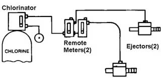
Multi-point application
A single Hidro system chlorinator/sulfonator, feeding multiple remote meters (two shown here), each connected to an ejector. Each remote meter-ejector pair (called a feed-point) operates independently. The maximum rate of gas at any given time drawn by all of the feed-points cannot exceed the single chlorinator/sulfonator capacity.
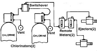
Multi-point Application using an Automatic Switchover Standby
Two Hidro system chlorinator/sulfonators feeding a switchover unit which is connected to multiple remote meter-ejector pairs (called a feed-point). When the current supply tank empties, the switchover unit automatically switches supply to the chlorinator/sulfonator connected to the full tank. Each feed-point operates independently and the maximum rate of gas at any given time drawn by all the feed-points cannot exceed the connected chlorinator/sulfonator capacity.
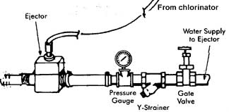
Injecting Chlorine into a pipe line using supply pressure
|
A Hidro system chlorinator/sulfonator system shown here feeding a pipe line using supply pressure. The pressure of the water supply to the ejector should be at least 40PSI greater than the water pressure of the line into which the chlorine solution is being injected ("back pressure") in order to create a sufficient vacuum in the ejector. |
Injecting chlorine into a pipe line using a
centrifugal pump
A Hidrosystem chlorinator/sulfonator system feeding a pipe line using a centrifugal pump. Note the location of gate valves for easy Y-strainer cleaning and practical pump maintenance.
NOTE: The pump suction should be 5 feet away from the ejector injection point. On larger pipe diameters of 6 inches or greater, a distance of 10 times the pipe diameter should be maintained so that chlorinated water is not recirculated through the booster pump.

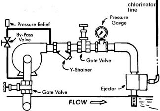
Injecting Chlorine into a pipe line using a turbine positive displacement pump
A Hidro system chlorinator/sulfonator system feeding a pipe line using a turbine positive displacement pump. The pressure relief valve must discharge to a drain or outside of the building. Note the by-pass of the piping from the pump discharge through a by-pass valve back to the suction side of the pump.
Note 1: The by-pass valve must never be completely closed.
Note 2: The pump suction and the ejector must be installed into the side of the pipe line, not the top of the main.